
Ultra-Narrowband Optical Bandpass Filters with Large Format and Improved Temperature Stability
Sophisticated monitor and deposition methods enable multi-cavity narrowband filters that push the envelope of performance.
Hard coated ultra-narrowband optical filters made using modern plasma processes offer much improved transmission, temperature stability and out of band blocking as compared to legacy soft coatings. These filters are used in optical systems as diverse as LIDAR (light detection and ranging), Doppler shift detection of plasma velocity, laser cleanup, chemical and gas sensing, as well as for cutting-edge astronomy and instrumentation applications.
Ultra-narrowband filters exhibiting square passbands for the NIR were pioneered during the telecom industry in the 1990’s but, until recently, have not been viable in large format sizes. Larger filters can be demanding to manufacture due to uniformity constraints, but are highly sought after for instrumentation purposes. Narrowband filters with compulsory operation in the Visible and UV present an added challenge due to loss and scatter; the deposition control system must be adept to deal with lower levels of light used for optical monitoring.
At Alluxa, we have developed novel deposition techniques to overcome these issues and accommodate large format requirements, resulting in very square ultra-narrowband filters. Our methods incorporate a sophisticated computer-controlled variation of the turning point method1, where the filter is constantly measured at a single wavelength and errors in prior layers are compensated in real time at the current layer. In this way, optical thickness is tightly controlled, allowing for highly reproducible square top filters with low ripple which consistently match theory.
Practical commercial limits to ultra-narrows are in the 50mm to 100mm diameter range. Larger formats are possible, but the costs can be prohibitive.
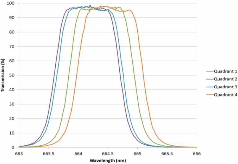
Figure 1. Uniformity plot for a 75mm-diameter measured at four quadrants in from the edge.
Figure 1 shows the measured variation of a 75mm format ultra-narrow filter at four separate quadrants starting 12.5mm from the edge. Center wavelength varies < 0.06% for all positions and bandwidth (FWHM) is controlled to better than 0.02nm.

Figure 2. Spherical tokomak from plasma fusion research.
Advancements in monitoring methods have enabled narrowband filters to be fully customizable. For example, a filter can be fabricated to transmit very discrete wavelengths of light for a plasma physics application, allowing for superior contrast imaging of the ELMs (edge localized modes) in a tokomak (see Figure 2). A custom narrowband filter with roughly 2nm bandwidth and T > 90% has contributed to a significant increase in temporal and spatial resolution for a system measuring carbon impurities in ELMing plasmas.2 Imaging contrast can be further enhanced by increasing passband transmission while reducing the bandwidth of the filter.
Alluxa continues to push the manufacturing limits for ultra-narrow filters, producing exceedingly narrow bandwidths with exceptional transmission. Figure 3 illustrates measurement of a 0.3nm multi-cavity filter which can be angle-tuned to preserve p-polarization performance.
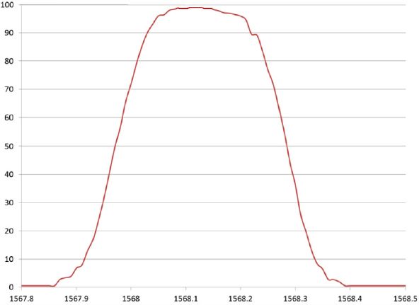
Figure 3a. Ultra-narrow, 0.3nm, bandpass filter at 0°.
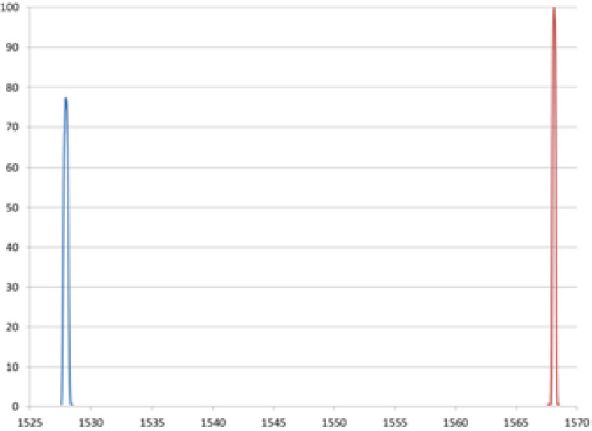
Figure 3b. Ultra-narrow, 0.3nm, bandpass filter angle-tuned by 26° for p-polarization.
It is important to note that commercially available instruments become incapable of measuring the filters effectively at these narrow bandwidths. Specialized metrology techniques are often required to verify performance, as described elsewhere in application notes.3,4
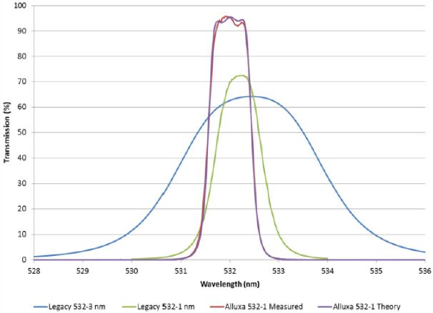
Figure 4. Measured performance for a 0.94nm three-cavity ultra-narrowband filter compared with results of other known deposition methods for narrowband filters.
When comparing our ultra-narrow results to those made with alternative technologies, the difference is quite remarkable. Figure 4 shows the measured versus theoretical response of a 532nm three-cavity flat-top band pass filter fully blocked from 350nm to 900nm at OD4 levels (an optical density of 4). Shown alongside are typical state-of-the-art narrowband filters from legacy deposition processes, such as ion-assisted electron beam.
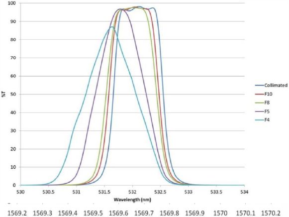
Figure 5. Filter function as calculated for various F-numbers.
For practical discussion, real world filters are often used with some defined cone angle instead of a perfectly collimated source. All thin-film filters exhibit a shift in the wavelength of the passband which is dependent on the angle of incidence. The net effect of using a larger cone angle is rounded slopes in conjunction with the shift. The angle shift can be minimized by using design techniques that take into account refractive index of the total design. An example is shown in Figure 5, where a filter with F number as low as F5 is shown to still retain a portion of its nominal shape. As indicated by the plot, filters to be used in low F-number systems should be biased slightly higher for the central peak to achieve optimal transmittance.
Unlike narrowband filters made with other deposition technologies, our ultra-narrowband filters offer wide and deep blocking performance at levels up to and beyond OD6 without sacrificing transmission performance. Typical performance specifications require blocking in the range of 400nm to 900nm outside of the passband at levels of OD4, OD5, or OD6; this is largely dependent on the detector response and can be tailored to individual system needs. Figure 6 demonstrates a typical blocking curve.
Our filters are routinely exposed to both telecom and MIL standard operating conditions (as used by the US Department of Defense). The MIL standard for operation in humid environments specifies a requirement of 10×24h temperature/humidity cycles with extremes of 60°C/95% relative humidity, 30°C/95% relative humidity, and 20°C/95% relative humidity. The Telcordia GR-1221 Damp Heat UNC requirement is 2000h at 85°C/85% relative humidity. The filters we produce show no measurable change to spectral performance or physical appearance after enduring these cycle tests. In addition to environmental testing, our filters also meet Department of Defense durability requirements (as defined by MIL 48497A).
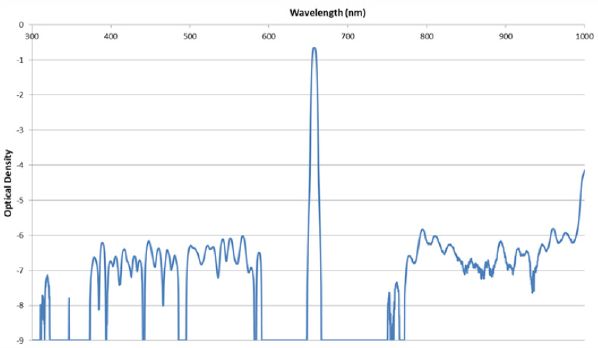
Figure 6. Blocking curve with OD6 levels out of band.
Our hard-coated ultra-narrowband pass filters have a very low wavelength dependence on temperature. It varies depending on the substrate choice and the type of coating design, but for a typical 532nm ultra-narrowband filter on a Schott BK7 glass substrate, the center wavelength will shift approximately 2.5pm/°C. Figure 7 further demonstrates the effect of shift with increasing temperature for a 659.2nm centered ultra-narrow – this particular filter exhibits an average shift < 4.2pm/°C from room temperature (27°C) to 105°C. Lower values of temperature shift can be created on request by optimizing the design parameters.
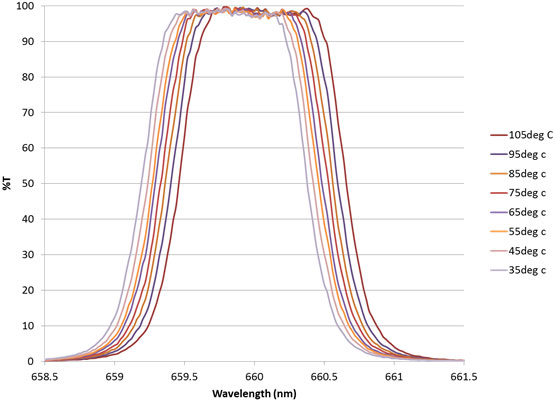
Figure 7. Measured filter performance for 1.2nm narrowband, heated from room temperature to 105°C.
In summary, our computer-controlled method of thin-film deposition allows us to create multi-cavity filters with greater wavelength precision, superior contrast, and improved performance in unyielding environments. Our future work will focus on further decreasing the bandwidths of our high-transmission, hard-coated flat-top filters to values of less than 0.5nm, and further improving filter functions and transmission levels. We also plan to explore the reduction of the transmitted wavefront error, a major culprit in image distortion.
References:
[1] H. A. Macleod, D. Richmond, The effects of errors on the optical monitoring of narrow-band all-dielectric thin film optical filters, Opt. Acta 21, p. 429-443, 1974.
[2] S.L. Allen, W.H. Meyer, G.D. Porter, and J. Howard, Carbon ion flow measurements in DIII-D divertors by coherence imaging, US DOE in conjunction with Lawrence Livermore National Laboratory and Australia National University, 2013. https://e-reports-ext.llnl.gov/pdf/775621.pdf
[3] Alluxa Engineering Staff, New metrology techniques for advanced thin film optical filters, Alluxa White Paper Series, 2012. https://alluxa.com/learning-center
[4] T. Burt, Characterizing sub-nanometer narrow bandpass filters using a Cary 400/500, Tech. Rep. SI-A-1193 Agilent Technologies Inc., 2011.
Why Alluxa?
Alluxa’s team of experts has delivered key innovations to the field of optical thin-films. In addition to designing and constructing all of our own custom optical thin-film coating equipment, we invented a novel plasma deposition coating process that both increases the performance of our optical filters and decreases the time it takes to produce them.
By combining these innovations with state-of-the-art automation, proprietary control algorithms, and precision monitoring during the coating process, we are able to deliver low-cost, high-performance, custom thin-film optical filters for any application.
Contact Alluxa for more information at info@alluxa.com
or visit our website at https://alluxa.com
All content copyright ©2020 Alluxa, Inc.