

Thin-Film Interference Filters for LIDAR
High-performance, ultra-narrowband interference filters improve LIDAR signal-to-noise ratios.
Arguably the most versatile active remote sensing technique, LIDAR (Light Detection and Ranging) is used across platforms and across disciplines. Long known to be one of the most important technologies in Earth and atmospheric sciences, LIDAR is now being utilized for obstacle avoidance in autonomous vehicles, urban planning, security, infrastructure development, and many other applications. This surge of novel uses recently forced an influx of technological advancements and a renewed interest in LIDAR sensors that is driving down the cost and making the technology more accessible.
In order to keep up with the technology, LIDAR interference filters must be designed to maximize signal-to-noise ratios by reliably isolating the target LIDAR return signal. Recent advancements in thin-film, ultra-narrow bandpass interference filters have allowed for >95% transmission, less than 0.1 nm bandwidths, steep edges, a square spectral shape, wide range blocking measured at > OD 8 (-80 dB), uniform coatings, and minimal thermal dependence. High performance LIDAR interference filters have greatly improved signal-to-noise ratios and reduced the need for multiple filtering techniques.
1. Principles of LIDAR
1.1 The Basics
A ‘time of flight’ technology, most LIDAR sensors scan a pulsed laser across the environment and determine the return time of the reflected signals. These laser altimeters calculate the return time based on the precise position and orientation of the sensor as the signals are emitted and received (Figure 1). To accomplish this, a LIDAR system requires 5 basic components: a laser, either a mechanical or software based scanning system, a receiver or photodetector, a GPS unit, and a high-precision clock. Aerial LIDAR systems also require an inertial measurement unit (IMU) to determine orientation.
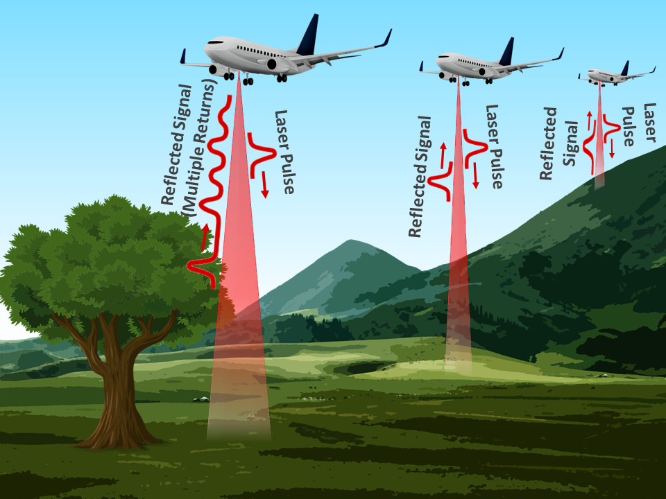
Figure 1. An aerial laser altimeter system used for mapping topography and canopy cover.
Image credit: Alluxa
The basic equation used to determine the distance between the object and the sensor is:
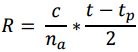 Where R is the range in meters, c is the speed of light, na is the index of refraction of air, t is the time when the signal returns, and tp is the time when the pulse is emitted.
The result is a data point cloud (Figure 2) that can be used to create high-resolution digital elevation models (DEMs) or 3D images of features in the surrounding environment. Because the laser beam is generally expanded as it is emitted, a single LIDAR pulse can encounter multiple objects, resulting in multiple reflected signals. Depending on the associated software, LIDAR systems will either record these returns as discrete points, or will display the data as a waveform showing each return as a function of time (Figure 1).
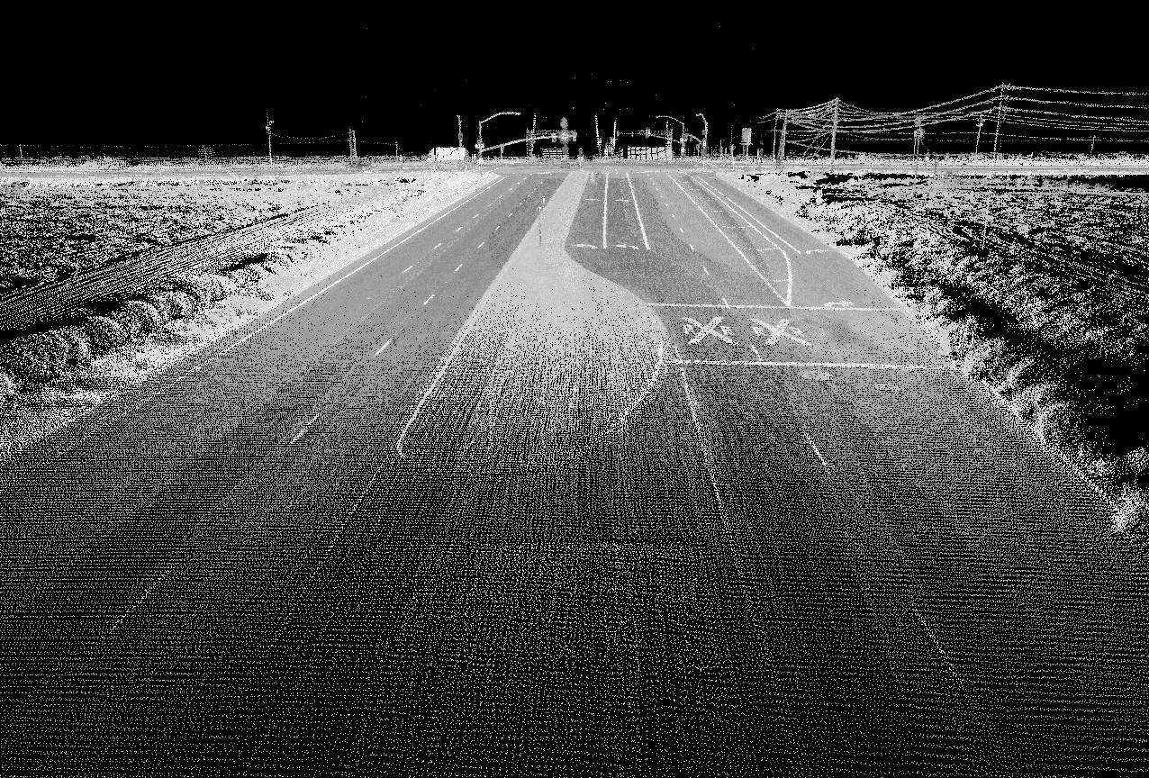
Figure 2. LIDAR data point cloud showing a detailed 3D street view.
Image credit: Oregon State University
1.2 Filtering Technologies
In order to function during daylight hours or in the presence of stray light, a filtering technology must be integrated into the LIDAR receiver to isolate the return signal. Options include interference filters, Fabry-Pérot interferometers, Fabry-Pérot etalons, spectrometers, atomic line filters, and filtering algorithms. LIDAR systems requiring a high level of precision generally include a combination of two or more of these filtering techniques.
Filter choice depends on the exact LIDAR application and system requirements. However, many LIDAR systems rely on hard-coated, thin-film interference filters because of their inherent durability and lack of a need for maintenance or calibration [2]. This is an important consideration since LIDAR sensors can be mounted on satellites, airplanes, UAVs, autonomous vehicles, and other platforms that require the sensor to function under harsh environmental conditions with little to no maintenance.
2. LIDAR Interference Filters
2.1 Bandpass Design
Thin-film interference filters are made by depositing alternating layers of materials with contrasting indices of refraction onto a substrate. As light makes its way through the filter, part of the light reflects at each layer, resulting in internal interference. Depending on the thicknesses and configuration of the layers, the net result is that certain wavelengths of light are transmitted through the filter, while others are either absorbed by it or reflected off of it.
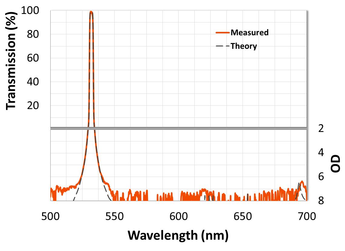
Figure 3. A hard-coated, flat-top, 532 nm ultra-narrow bandpass interference filter with > 95% transmission, steep edges measured to OD 7 (-70 dB), and wide-range OD 7 blocking.
Ultra-narrow bandpass filters are the most common type of interference filter used to isolate LIDAR return signals (Figure 3). These filters can be designed with bandwidths as narrow as 0.1 nm without sacrificing transmission, which is typically greater than 90%. The basic design relies on Fabry-Pérot resonant cavities, where two dielectric reflectors composed of pairs of high and low index layers, each with an optical thickness of ¼ wavelength, are symmetrically separated by a spacer composed of one or more ½ wavelength thick layers. This combination of mirror pairs symmetrically separated by a spacer forms a single cavity. When a single cavity is used in the design, the result is a filter with a peaked spectral shape. However, as more cavities are added, the passband becomes more square, resulting in the transmission spectrum having a flat top, steeper edges, and greater attenuation just outside the passband (Figures 4 & 5). Multi-cavity designs therefore allow for more precise transmission of the target signal and greater LIDAR signal-to-noise ratios.
By tightly controlling optical thickness during the coating process, Alluxa is able to reliably reproduce high-transmission flat-topped ultra-narrow filters with low passband ripple that consistently match theory. This is accomplished through the use of a sophisticated software-controlled system that tracks and optimizes the optical thickness of each layer in real time.
2.2 Out-of-Band Blocking
In order to isolate the target signal from sunlight and other extraneous light sources, LIDAR interference filters must be specified with wide range out-of-band blocking. Blockers are designed using dielectric reflectors where the mirror pairs are stacked and ultimately manipulated so that the filter attenuates light across broad wavelength regions. Specific blocking levels and ranges depend on the application and will be discussed in section 2.4
2.3 Interference Filters for Specific LIDAR Applications
Laser altimeters
Laser altimeters detect the laser pulse echo when it is reflected off of an object, the ground, or water and are the most common type of LIDAR sensors. For topographic applications, an eye safe 1064 nm pulsed Nd:YAG laser is generally emitted and reflects at the same wavelength. Due to multiple returns, the resultant point cloud is used to map both the bare ground and the canopy.
For bathymetric applications, a 532 nm frequency-doubled pulsed Nd:YAG laser capable of penetrating the water’s surface is used either alone or in conjunction with a 1064 nm laser that reflects off of the surface. A 532 nm laser can also be used to monitor glaciers and ice sheets over time, as seen with the Advanced Topographic Laser Altimeter System (ATLAS) on board NASA’s soon to launch ICESat-2 mission.
Ultra-narrow interference filters used for laser altimeters should have a center wavelength (CWL) at the laser line and a Full Width Half Maximum (FWHM), or bandwidth between the points where edges measure at 50% of peak transmission, that is 1.5 nm or narrower. Out-of-band blocking depends on the laser wavelength and specific instrument. Greater than OD 6 (-60 dB) blocking from 300 – 1300 nm is common in many sensors while > OD 5 over a narrower wavelength range is sufficient in others. Multi-cavity designs are ideal for these systems; however, single-cavity filters remain a cost saving option (Figures 4 & 5).
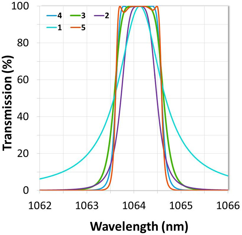
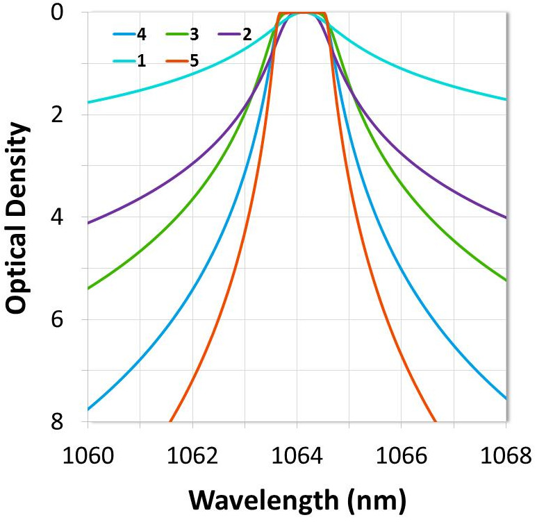
Figures 4 & 5. The effect of cavity count on filter shape and out-of-band blocking. Higher cavity counts result in steeper edges, deeper blocking, and a square spectral shape.
LIDAR for autonomous vehicles
Stemming from the basic laser altimeter technology are the LIDAR sensors integrated into autonomous vehicles (Figure 6). These generally utilize a 905 nm or 1550 nm pulsed laser along with a photodetector, such as a silicon avalanche photodiode. They can either have a mechanical scanning system capable of capturing a 360 degree field of view (FOV) or they can be fully solid state. Solid state LIDAR units are small, inexpensive, and have no moving parts due to the software based scanning system. Accuracy and resolution tend to be comparable to mechanical units, with the main trade off being a reduced FOV. However, this can be offset by mounting multiple units onto a single vehicle.
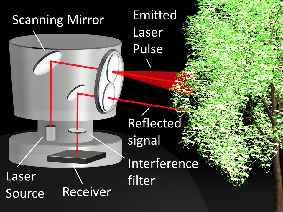
Figure 6. Diagram showing a LIDAR system for an autonomous vehicle.
Image credit: Alluxa
Filter specifications for mechanical LIDAR systems are similar to those for laser altimeters. However, fully solid state systems generally rely on a filtering algorithm to isolate the reflected signal. In some cases, this can be used in conjunction with a wideband interference filter that has > OD 4 wide-range out-of-band blocking.
Fluorescence LIDAR
Fluorescence LIDAR units detect the emission of a variety of naturally occurring molecules, such as chlorophylls, carotenoids, phycobilins, or other photosynthetic pigments, when excited by a laser. In aquatic settings, this allows for the detection of toxic red tide events or increased concentrations of algae and cyanobacteria, which could indicate hypoxia. On land, fluorescence LIDAR is frequently used in vegetation studies and to assess the conservation status of cultural monuments.
Fluorescence LIDAR is also used in atmospheric research to study complex organic aerosols, airborne pathogens, and atmospheric gases. In addition, NASA has recently proposed a fluorescence LIDAR technology, the Bio-Indicator LIDAR Instrument (BILI), for detecting bio-signatures and organic molecules on other planets.
In these instruments, bandpass CWL and FWHM are placed according to the fluorescence emission spectrum of the molecule of interest. In order to maximize the signal-to-noise ratio, the laser line and extraneous light should ideally be attenuated to a level of OD 6 or greater for aquatic or terrestrial studies, while deeper blocking levels are needed for atmospheric systems.
Mie, Rayleigh, Raman, and Doppler Atmospheric LIDAR Systems
Mie and Rayleigh LIDAR instruments are used for air quality monitoring. They are ground based or forward facing aerial systems that detect the elastic Mie or Rayleigh backscatter of aerosols and homonuclear diatomic gases at laser wavelengths of 355nm, 532nm, and 1064nm. Doppler LIDAR is often integrated into these systems and determines wind velocity by detecting the Doppler shift of the elastic backscatter from aerosols or gases.
Raman LIDAR instruments detect the inelastic rotational and vibrational Raman scattering that occurs when molecules of interest are excited by a laser. Interference filters can also be used to isolate the pure rotational Raman signal, allowing for the determination of particle extinction, air temperature, and other properties [5,7].
Because atmospheric LIDAR systems rely on relatively weak backscatter signals, every effort must be made to maximize the signal-to-noise ratio. The basic form of the LIDAR equation for atmospheric systems indirectly highlights the importance of using high-performance interference filters:
 Where P(R) is the signal power, K is the system efficiency, G(R) is the measurement geometry, Β(R) is the backscatter coefficient, and T(R) is the transmission term, with all except K being a function of range. Only K and G(R) are able to be improved through system modifications because the other two terms describe inherent atmospheric optical properties [6]. Since system efficiency relies on receiver efficiency, using high-performance interference filters is one simple way of improving signal power.
While OD 6 or 7 blocking can be sufficient for some Mie and Rayleigh LIDAR sensors, it is recommended that Raman LIDAR filters have blocking that exceeds OD 7 or 8 [1,5]. This is especially necessary at the laser wavelength so that the stronger elastic backscatter signals are blocked. However, the tight transition from > 90% transmission at the Stokes or Anti-Stokes branch of the Raman signal to > OD 7 blocking at the laser line also necessitates a high-cavity-count design to ensure sufficient steepness.
Veselovskii et al. recently used an ultra-steep Raman LIDAR interference filter manufactured by Alluxa to isolate a relatively temperature insensitive portion of the Anti-Stokes pure rotational Raman spectrum for N2 and O2 following 532.12 nm laser excitation. This filter was designed with a slope of < 0.1% of edge wavelength from 90% transmission to OD 4. In this particular case, > 95% transmission in the passband allowed the authors the option of using two identical interference filters in series in order to achieve OD 8 rejection of the elastic signal with a < 1 nm transition to the passband [5].
Differential Absorption LIDAR (DIAL)
DIAL units take advantage of the absorption spectra of water vapor and atmospheric gases in order to determine their concentrations. DIAL systems use two different lasers, the first tuned to an on-resonance, or high-absorption, wavelength for the target molecule, and the second is tuned to an off-resonance wavelength. The on and off-resonance wavelengths are generally less than 1 nm apart, which allows researchers to assume that any measured backscatter differences are due to absorption by the species of interest. This allows for a concentration profile to be determined from the backscatter ratio as a function of range.
Because the near and far channels of DIAL systems are very close in wavelength, these systems generally require ultra-narrow interference filters for sunlight attenuation, while Fabry-Pérot etalons are used to separate the channels [4]. The ultra-narrow interference filters commonly have a FWHM of < 0.5 nm and > OD 6 wide range out-of-band blocking, while the multi-cavity designs maximize sunlight attenuation at wavelengths close to the passband.
2.4 Measuring Ultra-Narrow Bandpass Filters
The light sources and spectral resolution of most spectrophotometers and other grating based measurement systems are insufficient for measuring and evaluating steep edges, blocking beyond ~OD 6, or ultra-narrow bandpass filters. For example, if the filter edge transition from high transmission to deep blocking is close to the spectral resolution of the spectrophotometer, the filter edge will not resolve properly and the actual steepness will not be reflected in the measurement. This is also true for filters with less than ~1nm FWHM. For these, the effect of edge smearing is further compounded since the bandwidth is also close to the spectral resolution of the instrument. This ultimately results in an unresolved passband, with the final measurement showing a rounded off peak and relatively low transmission.
In standard spectrophotometers, spectral resolution can be improved by introducing narrow apertures and by decreasing the spectral bandwidth. However, these options also reduce the light intensity, which decreases the signal-to-noise ratio and raises the noise floor of the measurement, making blocking more difficult to measure. The noise floor of many of these instruments is able to be lowered by completely removing the apertures, attenuating the reference beam, and increasing the spectral bandwidth. This method is useful for measuring wide blocking regions specified at up to ~ OD 6 or 7, but should not be used to evaluate the passband or filter edges since the coarse spectral resolution will result in dramatic edge smearing and an inaccurate bandwidth.
High-performance and ultra-narrow filters therefore require more sophisticated measurement technologies. One well known method for measuring ultra-narrow bandpass filters involves using a tunable laser to precisely measure filter transmission at each wavelength in its range. However, since the wavelength range of most tunable lasers is relatively narrow, multiple lasers would need to be used to measure the full transmission and blocking ranges of a single filter. Therefore, this method is not ideal for high-volume manufacturing scenarios.
Fortunately, Alluxa has recently developed a new system that is capable of accurately measuring our highest-performance and narrowest bandpass filters, while still being robust enough for use in a high-volume manufacturing setting (Figure 7). The HELIX Spectral Analysis System is capable of resolving bandwidths of less than 0.1 nm, transitions as steep as 0.4% of the edge wavelength from 90% transmission to OD 7, and blocking ranges that are greater than OD 8. The HELIX system is especially useful for evaluating the true performance of ultra-narrow filters for Raman LIDAR and other demanding applications that require incredibly steep edges and greater than OD 8 blocking.

Figure 7. A 607.4 nm LIDAR interference filter for an N2 Raman channel measured with both a standard spectrophotometer and Alluxa’s HELIX Spectral Analysis System. The HELIX System is able to resolve filter edges all the way to OD 7 (-70 dB).
3. Additional Filter Considerations
3.1 Uniformity
In order to maximize coating uniformity, the deposition process and chamber geometry must be precisely controlled. When uniformity is not controlled, layer thicknesses vary across the surface of the filter, resulting in a location-dependent wavelength shift of the filter spectrum across the clear aperture of the part. Eliminating this wavelength shift is especially important for narrowband LIDAR interference filters due to the precise nature of the LIDAR return signals.
Accurately controlling uniformity is a multivariable problem. Common methods include changing coating chamber geometry, such as the distance or angle between the source material and the substrate, or introducing a physical mask into the coating chamber. Further changes to uniformity can be made by changing coating process variables such as temperature and deposition rate, but these changes can cause other complications in the deposition process that could adversely affect the final product.
Alluxa’s advanced uniformity control system minimizes location-dependent wavelength shift during the coating process in order to achieve precision uniformity over a large area. This results in a filter with minimal spectral variation across the clear aperture (CA), even for large-format parts (Figure 8).
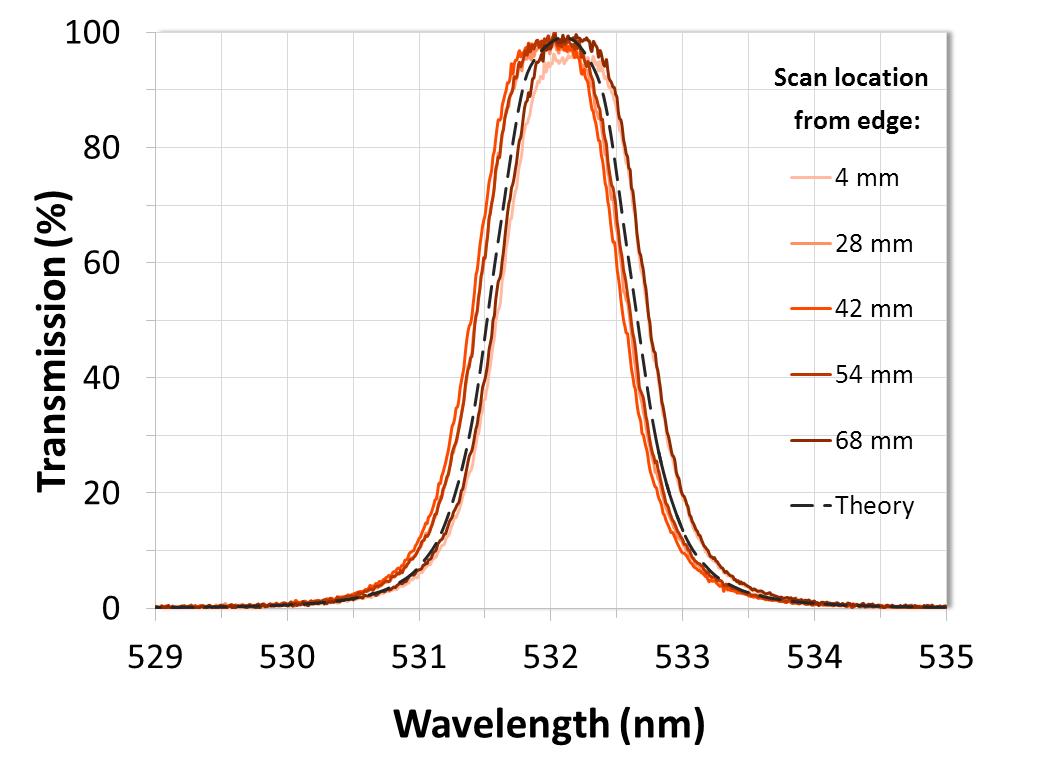
Figure 8. Measured results of a 72 mm diameter ultra-narrow filter manufactured using Alluxa’s advanced uniformity control system demonstrating < 0.035% variation in CWL over the clear aperture.
3.2 Temperature Dependence
Aerial and ground based LIDAR systems operate at temperatures that can range from -40° C to +105° C, while satellite LIDAR operating ranges depend on the orbit and thermal control system of the satellite. Therefore, any interference filters integrated into systems that operate at extreme temperatures should be designed to maximize temperature stability.In standard interference filters, extreme temperatures result in the expansion or contraction of the thin-film layers, resulting in a shift in wavelength of the passband. This shift can be dramatic unless the filter has been specifically designed to operate in harsh environments.
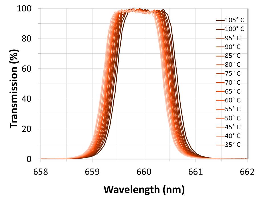
Figure 9. Measured performance of a narrowband filter when heated from room temperature to 105°C.
Alluxa’s hard-coated ultra-narrowband interference filters demonstrate a very low temperature dependent wavelength shift that tends to vary between 2pm/°C and 5pm/°C within the operating range of most LIDAR instruments (Figure 9) [3]. However, thermal stability can be improved even further by modifying material ratios and other design properties, or by choosing a substrate material that has a higher Coefficient of Thermal Expansion (CTE) than the CTE of the coating. Post deposition annealing can also aid in both thermal and chemical stability. During this process, the thin-film layers are thermally expanded while the materials are further oxidized, resulting in a reduction of coating stress.
4. Other Thin-Film Optical Components for LIDAR
In addition to bandpass interference filters, LIDAR systems utilize mirrors, dichroic filters, and other high-quality thin-film optical components. Many LIDAR sensors use high-reflectivity dielectric scanning mirrors with > 99.5% reflection, while ultra-light beryllium mirrors are ideal for fast scanning systems. Dichroic filters with regions of high transmission and high reflectivity, separated by a steep edge transition, direct the return signal to the appropriate receiver channel. In order to optimize system efficiency, the performance of these optical components should also be taken into account when designing a LIDAR sensor.
5. Summary
Driven by a multitude of new applications, LIDAR is becoming more efficient, affordable, and accessible than ever. Recent technological advancements have seen dramatically increased accuracy and resolution, even in systems that are small enough to be discretely hidden within the side mirrors of self-driving cars. Thin-film interference filters have kept up with the technology through state-of-the-art design and coating techniques, advanced measurement systems, tight uniformity control, and minimal thermal dependence. For any LIDAR instrument, Alluxa’s high-performance interference filters will maximize signal-to-noise ratio and system performance.
Literature Cited
[1] Hauchecorne, A., Keckhut, P., Mariscal, J., C., d’Aameida, E., Dahoo, P., and J. Porteneuve. (2016). An innovative rotational Raman LIDAR to measure the temperature profile from the surface to 30 km altitude. EPJ Web of Conferences, 119, 06008. DOI: 10.1051/epjconf/201611906008.
[2] Kovalev, V. A. and W. E. Eichinger (2004). Elastic LIDAR: Theory, practice, and analysis methods. John Wiley & Sons, Inc. Hoboken, NJ.
[3] Scobey, M., Egerton, P., Fortenberry, R., and A. Czajkowski (2013). Ultra-narrowband optical bandpass filters with large format and improved temperature stability. Alluxa White Paper Series. https://alluxa.com/learning-center.
[4] Spuler, S. M., Repasky, K. S., Morley, B., Moen, D., Hayman, M., and A. R. Nehrir. (2015). Field-deployable diode-laser-based differential absorption LIDAR (DIAL) for profiling water vapor. Atmos. Meas. Tech. 8: 1073-1087.
[5] Veselovskii, I., Whiteman, D. N., Korenskiy, M., Suvorina, A., and D. Perez-Ramirez. (2016). Implementation of rotational Raman channel in multiwavelength aerosol LIDAR to improve measurements of particle extinction and backscattering at 532 nm. EPJ Web of Conferences, 119, 17002. DOI: 10.1051/epjconf/201611917002.
[6] Wandinger, U. (2005). Chapter 1: Introduction to LIDAR. LIDAR: Range-resolved optical remote sensing of the atmosphere. Edited by Weitkam, C. Springer Science+Business Media, Inc. New York, NY.
[7] Wandinger, U. (2005). Chapter 9: Raman LIDAR. LIDAR: Range-resolved optical remote sensing of the atmosphere. Edited by Weitkam, C. Springer Science+Business Media, Inc. New York, NY.
Why Alluxa?
Alluxa’s team of experts has delivered key innovations to the field of optical thin-films. In addition to designing and constructing all of our own custom optical thin-film coating equipment, we invented a novel plasma deposition coating process that both increases the performance of our optical filters and decreases the time it takes to produce them.
By combining these innovations with state-of-the-art automation, proprietary control algorithms, and precision monitoring during the coating process, we are able to deliver low-cost, high-performance, custom thin-film optical filters for any application.
Contact Alluxa for more information at info@alluxa.com
or visit our website at https://alluxa.com
All content copyright ©2020 Alluxa, Inc.
